Applications
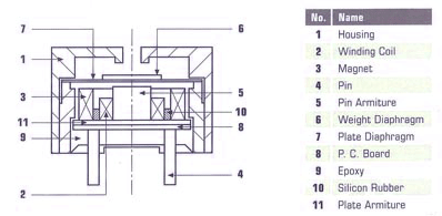
SANCO Products line of miniature magnetic transducers offer the highest quality and reliability at a cost effective price. SANCO`s extensive line of transducers include devices that are sealed for wave and wash processes, have side sound ports, and include a variety of different sizes to help meet all your design parameters.
|
|
SIGNAL INPUT POLARITY
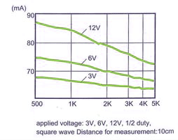
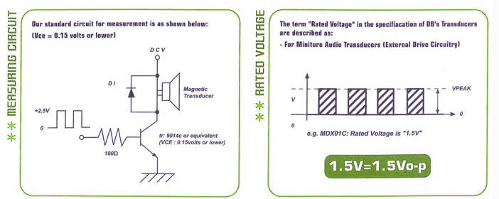
If the voltage signal input Vp-p is applied to our transducer with the polarity reversed, a sound will be generated but it will not always meet the catalog specifications for the sound pressure level. This is because the reversed polarity input changes the magnetic force direction from [attract" to [repulse" or vice versa, which can cause the resonant frequency to deviate from its original point and produce variations in the sound pressure level. However, if the voltage signal input alternates from positive peak to negative peak (Vp-p), the reversed polarity will have no effect on the sound produced. How frequency response characteristics are affected by changing the input of the amplitude. Some Design engineers do not drive audio transducers at the rated voltage recommended by the manufacturer. In most cases this is due to the voltage available relative to the customer`s specific application.
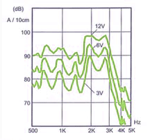
Our data sheets shows the frequency characterist with respect to the rated voltage. When different amplitudes are applied to a given transducer, the frequency characteristices change. Generally, as the input voltage amplitude decreases below the rated voltage, the resonant frequency (fo) rises. Conversely as the input voltage increases above the rated voltage, the resonant frequency (fo) falls. The basic resonant frequency of a specific transducer is a fixed value relative to its acoustic design. As a result, at lower than rated voltage the frequency response band tends to narrow, and at higher voltage values the frequency band tends to be wider. Consequently if the input voltage is too low, shifting the resonant frequency higher, the original rated frequency (i.e. 2,048Hz) may not fall within the frequency band. Thus the sound output will be well below the rated SPL.
|
|
SOUND PRESSURE
The sound producing devices like our sound transducers are generally used in certain enclose to have an appropriate resonance chamber in front of the sound producing device, it is possible to meet the requirements to a certain extent, for instance, to obtain an increased sound pressure, improved response in wider range of frequencies, or softened sound output. Design such resonator called elmholtz Resonator" according to the following equation:
|

|
|
Designing the resonator to have such dimensions that the resonant frequency (fv) of the resonance chamber may be greater than the resonant frequency (fo) of the sound producing device, improves the frequency response in wider frequency range, increases the sound pressure and softens the sound output eliminating harmonic components. (These effects may not be obtained if fv is lower than fo, or reduced if fv is excessively higher than fo. For increasing the sound pressure only, it is recommended to set the fv two times as high as fo.)
|
|
To Allow to Respond to Wider Range of Frequency Input
Design>>
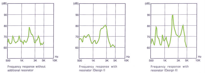
To broaden the frequency range to 2048~2700Hz, the resonator geometry is determined with an aim that the fv should be around 2700 Hz, slightly higher than the fundamental frequency of the transducer.
The sound hole diameter oD is set to 1.5mm. With those parameter set, the fv may be calculated as 2460Hz form the equation (I).
[Actual Measurement]
Frequency Response---.as shown in Fig. 1
fv-------------.2700Hz
As shown in Fig. 1, the frequency range may be broadened and a softer sound may be produced with the harmonic components considerably eliminated.
|
|
To Increase the SPL
Design>> To increase the SPL at the findamental frequency of 2048Hz, the resonator geometryis determined with an aim that the fv should be around 4100Hz, almost twice as high as the fundamental frequency of the transducer. The sound hole dimeter oD is et to 3.3mm. With those parameters set, the fv may be calculated as 4000Hz from the equation.
(I) Actual Measurement
Frequency Response---.as shown in Fig. 3
fv-------------.4000Hz
As shown in Fig. 3, the SPL range may be considerably increased, while the sound may become sharper due to its secondary harmonic components increased.
Fig.1 Frequency response without additional resonator
Fig.2 Frequency response with resonator (Design I)
Fig.3 Frequency response with resonator (Design II)
|
|
|
(II) Measuring circuit / Rated voltage
|
|
|
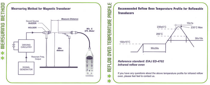
Measuring Method/ Reflow oven temperature profile
|
|
|