


Please Leave Us A Message
Privacy statement: Your privacy is very important to Us. Our company promises not to disclose your personal information to any external company with out your explicit permission.

Mr. Sam Duan
What can I do for you?

In using piezoelectric elements in audible output an application, a metal plate is attached to the ceramic element because the resonant frequency of the ceramic is too high to produce an audible tone by itself. This metal plate vibrates as shown in Fig. 1 due to the contraction and expansion of the piezo ceramic, and an audible signal is produced.
IMPEDANCE CHARACTERISTICSThe equivalent circuit for piezoelectric elements is shown in Fig. 3.The mechanical Resonance of the element is show by R, L, C where L and C determine the Resonant frequency (Fig. 3).  Because the shunt capacitor is larger than the series combination the total impedance is capacitive.

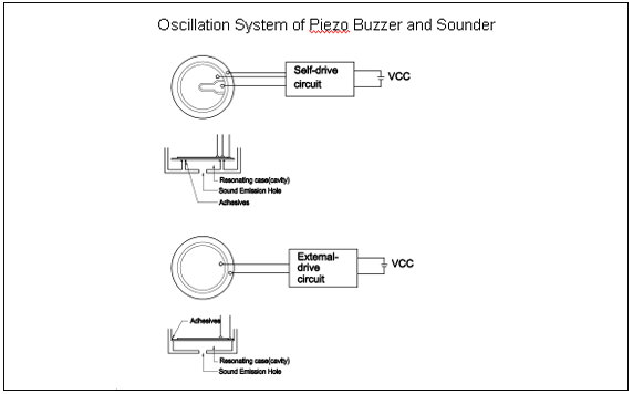
MODES OF VIBRATION AND SUPPORTING METHODS FOR THE SOUND ELEMENT Three principal modes of vibration can be created in the element depending on the style of mounting. This is illustrated in Fig. 2MOUNTING(1) Node Support The sound element shown in Fig. 2(a) is node mounted, allowing it to vibrate in a free state. The node, a circumference where no vibration takes place, is created as shown by the broken line in Fig. 1. Mounting at the node causes the least mechanical suppression of vibration, thus allowing the greatest amplitude. Hence this mounting method, as illustrated in Figure 5(a),gives the highest sound pressure output and the most stable oscillation frequency of the three choices. As a result, this is the most appropriate design for high output, self-drive applications.(2) Edge Support Fig. 2(b) shows the mode of vibration when the sound element is supported at the edges. In this mounting configuration, the whole sound plate vibrates up and down as is illustrated by the broken line in the diagram. Hence, the edge method as illustrated in Fig. 5(b), suppresses the fundamental resonant frequency by moving the node. This offers the possibility of a wide frequency response, and is most advantageously used with external drive.(3) Center Support Fig. 2(c) shows the mode of vibration when the sound element is supported at the center. As the main vibration area is forcefully supported, large sound pressure levels are not possible when this method is used. This too is appropriate for external drive but due to design difficulties center support is not useful as an alarm.CIRCUIT DESIGN CONSIERATIONS1. Driving Wave
3. DC Precaution
In order to prevent depolarization of the ceramic elements it is necessary that every precaution be taken to prevent them from being subjected to direct current.
4. High Voltage Precautions
Voltage higher than those recommended by specification can damaged the ceramic, even if applied for short durations. Due to the strength of the piezoelectric effect, high voltage can cause the crystals to break the sintered bonds, resulting in permanent damage. Significantly higher sound pressure levels will not be achieved by voltages higher than those recommended by specification.
5. Booster Coil Applications:
When using a booster coil, do not exceed voltage recommendations, as the coil will heat up, passing too much current to the transistor.
6. Shock:
Mechanical impact on buzzers or elements can generate high voltages that can seriously harm drive circuitry. Suitable diode protection is advisable in applications where mechanical shock is possible. Zener diode shown as Figure 7a; Schottky diode shown as Figure 7b.
7. Mounting Glue:
Proper application of mounting glue is necessary to produce adequate sound pressure levels.
8. Design of Resonating Case:
When an element is supported and has no case, the sound pressure level is small. This is because the acoustical impedance of the elements does not match that of any open air loading.
However, by building a resonating case, the acoustical impedance of the element and encased air can be matched. This case can be designed using the following
(Helmholtz`s equation)

fo = Resonant frequency of Cavity (Hz) c = Sound velocity 34.4 x cm/sec@24
a = Radius of sound emitting hole (cm) d = Diameter of support
h = Height of cavity(cm)
t = Thickness of cavity
k = Constant=~1.3
9. Electrostatic Capacitance
It is necessary to match the output impedance of the oscillator with the transducer impedance in order to get maximum sound pressure level from the transducer. The actual electrostatic capacitance can be calculated from the following formula.
C = pF
pF
D = Diameter of electrode (cm)
t = Thickness of ceramic (cm)
10. Soldering Recommendations
The desired location for soldering lead wires on an element is the point nearest to the edge of the silver surface. The desired location for soldering a lead to the metal plate is the area between the end of the plate and the end of the ceramic.
Below are the conditions for soldering.


Send Inquiry

Mr. Sam Duan
Tel:0086-574-83851068
Fax:0086-574-83851096
Mobile Phone:+8613957856201
Email:sales@sancoelectronics.com
Address:Rm10-9, No.580, Ningdong road, Huanhe business centre #2 building, Ningbo, Zhejiang
Related Products List
Mobile Site
Privacy statement: Your privacy is very important to Us. Our company promises not to disclose your personal information to any external company with out your explicit permission.
Fill in more information so that we can get in touch with you faster
Privacy statement: Your privacy is very important to Us. Our company promises not to disclose your personal information to any external company with out your explicit permission.